My home was undergoing reconstruction during 2022, and with a fresh start you get the opportunity to fix problems that plagued you before. The old building was constructed in the 1980s and with the brick and cement walls in India it is impossible to get a good Wi-Fi connection or add cabling to add additional access points. This time, I made sure to have at least one CAT6 cable going to each room, in order to be able to fix any dead spots by simply adding in access points in problem spots, and turning a bundle of wire into a home network system that handles terabytes of data each month has been a learning experience.
Equipment Rack
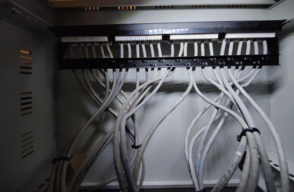
The first order of business for making this operational was to terminate the cables in order to be able to connect devices between them. According to my research, the recommended way to approach this was using a patch panel. A patch panel takes the 8 conductors on a CAT6 cable and turns them into female connectors that you can attach to your rack and ensures that the solid conductors aren’t stressed from moving around.

I then had to determine what switches I would need to handle all the traffic. I wanted a gigabit uplink on the minimum for all devices and had to provide power to 5 IP cameras, preferably over PoE. I ultimately decided to use a Netgear GS108PP switch for gigabit PoE for the cameras and a Netgear GS324 for the non PoE devices.

The heart of this setup was the Mikrotik hAP AC2. It has been my router of choice for a few years as it can comfortably NAT a gigabit connection, is extremely customizable due to RouterOS and draws only about 5w due to its quad core ARM CPU. The hAP however does not support being rack mounted, as it is meant for a SOHO setup. I fixed this problem by modeling and 3D printing a tray for the router that could be rack mounted ensuring that the setup stays cleaner overall.
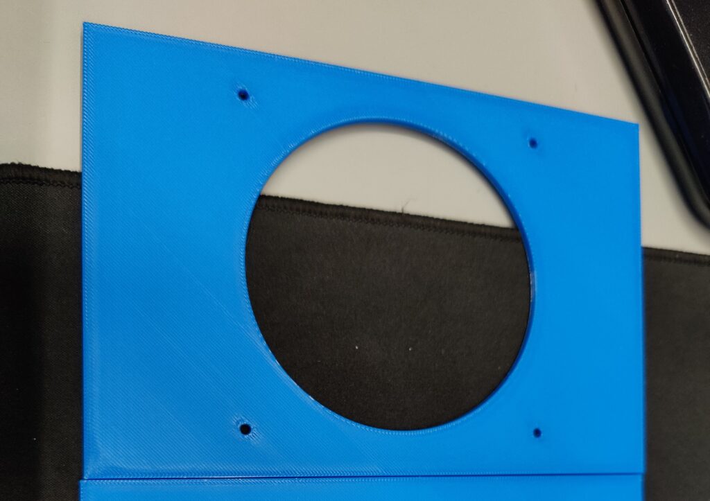
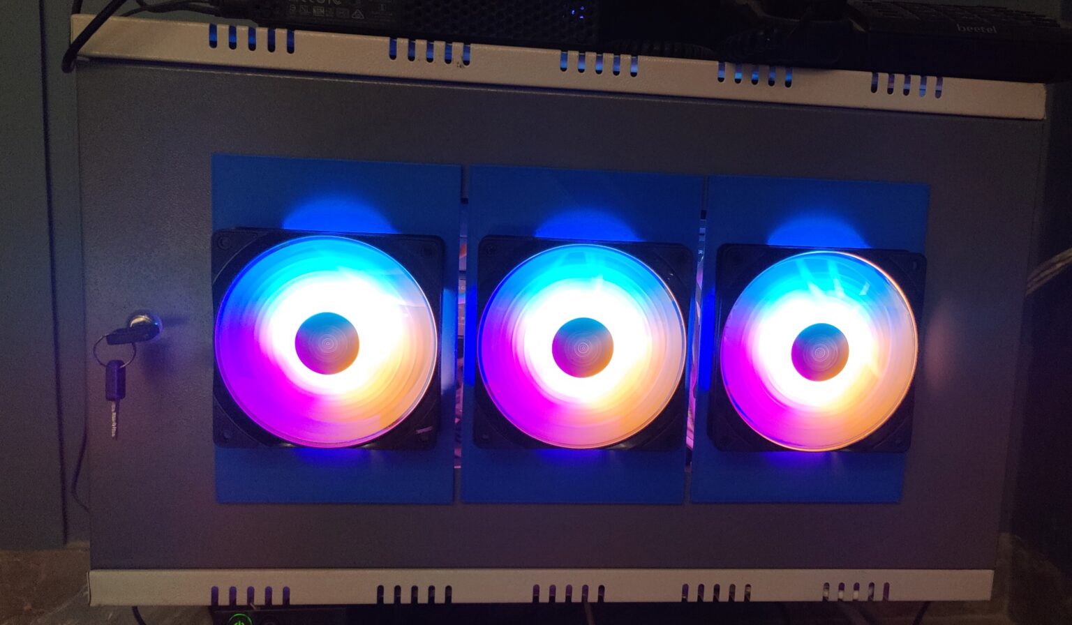
With the equipment installed I added an ESP8266 with a DS18B20 temperature sensor to the bottom of the GS324 in order to monitor temperatures in the rack, and noticed that the equipment could reach 40-50C during the summer months. This is an acceptable temperature for the equipment installed and within the operating specifications but I would prefer to have lower temperatures for power savings as well as equipment longevity, so I 3d printed plates with holes and mounting points for 120mm PC case fans that I could attach to the front of the rack in order to maintain positive airflow into the rack and keep things cool.

The 3 fans blowing on the equipment temperatures lowered to a much more acceptable 35C, ensuring that the equipment would work reliably and will not cause random issues due to overheating. I unfortunately could not disable the LEDs on the fans as they were wired in series with the motor but functionality comes before form.

After finishing installing everything inside the rack and connecting my server to the hAP, I was able to begin network configuration. I decided upon the following network layout.
10.0.0.0/23 - LAN
- 10.0.0.0/24 - DHCP
- 10.0.1.0/24 - Static IPs
10.0.2.0/24 - Cameras
10.1.1.0/24 - Wireguard
I decided to make a /23 subnet for the local network. This is because of the high number of static IPs in the network because of the 50 or so smart devices in the house along with other equipment such as printers and the access points. I also decided to put the cameras in their own network that does not have internet access in the interest of privacy. The cameras can be accessed from outside the network by simply connecting to the wireguard tunnel.
Access Points
The choice of access points was critical for this project. The options available in India were fairly lackluster, with most options being intended for ceiling or wall mounts, which would not work with my setup. I had previous experience with using OpenWRT as my routing platform of choice, and wondered if it could be used for access points as well. Looking around in the documentation, I found this page, which details how an OpenWRT device can be setup in order to act as a WAP. This information along with the usteer package, which uses 802.11v and 802.11v to aid devices to pick the best access point to connect to gave me a fairly stable and well performing wireless network. However, if I were doing another project like this, I would definitely look into enterprise WAPs instead. The OpenWRT APs lack any sort of features for management and updating and can be quite unstable between firmware revisions. The setup also requires far more manual setup and tuning than something like a proper WAP would and with more performance.
The final access point collection looked like this:
- 1 Xiaomi AX3200
- 1 Netgear R6350
- 4 TP-Link Archer C6 V3.2
All devices other than the Xiaomi are MT7621 devices, which is a quite mature target platform for OpenWRT and is quite stable. The Xiaomi AX3200 just obtained stable support for OpenWRT but also performs quite well, reaching near gigabit speeds with 802.11AX
#Final Thoughts
Creating this network has been an incredible learning experience that challenged both my hardware and software knowledge, as well as taught me quite a lot about how to plan for infrastructure and to chose suitable hardware. I would definitely recommend taking on a project like this as compared to simply hiring someone to do it for you, as it teaches you the ins and outs of your home network and allows you to quickly and easily modify or fix any problems you may have with it in the future.