My house has outdoor lights on the front façade as part of the overall design of the house. These lights were currently turned on manually at a regular time everyday, but someone had to go to turn them off for the night. This proved to be very inconvenient, and resulted in my dad asking me to create some sort of solution to automate the task. I started mapping out the problem in order to understand it better and to break it down into components in order to understand how this would be solved, and concluded the following things:
- There are 5 different lights in total, one being the lights for the parking and others for the facade.
- The parking lights need to be turned on when it gets dark during the day, for example during a rain storm or in the early evening
- Near sunset, all lights need to be turned on.
- At 11PM, only the lights in the driveway need to be turned on.
- Near sunrise, the driveway lights need to be turned off
With this information, I decided upon using a system that would use a light sensor in order to check what the current light status is outdoors and use that information along with the sunset and sunrise time of the day to determine when the lights are turned on and turned off.
I began creating a light sensor using a NodeMCU ESP8266 as the microcontroller of choice. It is a low power device with plenty of GPIO pins as well as having built in Wi-Fi, which makes it very easy to use along with the rest of the control infrastructure. I added a BH1750 which is a digital light sensor which communicates via serial peripheral interface to the microcontroller and provides it the ability to sense the light outside. This is a foundation on which is project is built as the time when the lights are triggered can vary based on the seasons and setting a fixed time for triggering would be unlike how a human would determine their state.
I used ESPHome to add functionality to the device. I did consider writing software for this myself that would communicate over MQTT but ultimately decided against it as ESPHome provides their own API for communication to HomeAssistant, and it would be one less component that would need to be maintained.
I then designed and 3d printed a case for the microcontroller using my Ender 5 Pro and Fusion360, and then used prusaslicer to print it out using PLA plastic. The case is built to snap together on both sides but I added tape as an additional layer of security.

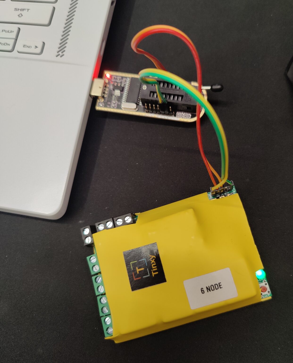
I then began to work on the hardware which would control the power to the lights. I had 5 individual lights that needed to be powered on and off, and decided to use a 6 relay smart switch in order to control them. I found a company based in Delhi called Tinxy that was manufacturing smart relay boards themselves along with writing the software for them, and decided that they would be perfect for the task at hand. I overwrote the factory software on the ESP8266 microcontroller on the smart relay board with ESPHome by soldering on header pins to allow a serial communication bridge and began experimentation.

According to the documentation provided by Tinxy, the board uses serial communication to communicate to another microcontroller onboard as the ESP8266 does not have enough GPIO pins in order to accommodate 6 relays, status LEDs, reset buttons and more. The communication to the microcontroller was a simple string which followed the following pattern.
#1100# ;Turn Relay 1 on
#1000# ;Turn Relay 1 off
#2100# ;Turn Relay 2 on
#2000# ;Turn Relay 2 off
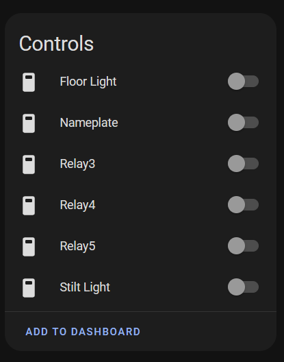
Using this, I created dummy switches in ESPHome which send these commands when the switch is turned on or off over the GPIO 1 and 3 pins which are for hardware serial TX on the ESP8266.

After adding the ability to trigger the hardware using HomeAssistant locally, I connected the relay board to mains voltage in order to test out if everything works as intended.

With the hardware portion out of the way, I was finally able to begin work on the software component of this project. I used HomeAssistant for handling the automation of the project as it provides a solid backbone to build software on and integrates very well with all of the components of the project.
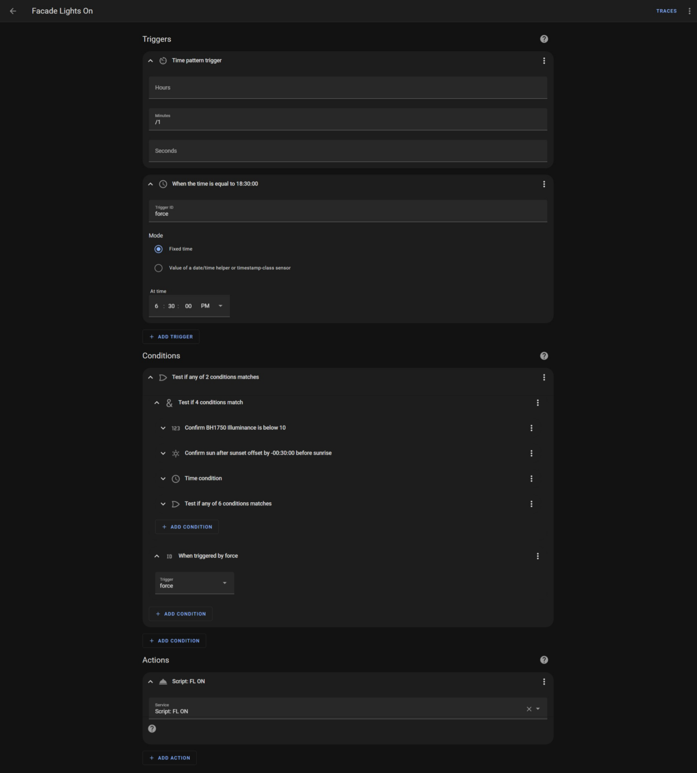
I began by mapping out what conditions need to be satisfied in order to determine what the state of the lights would be. I decided upon using the data from the light sensor, if the sun has set or risen, the current status of the switches as well as a time condition in order to make sure that the lights still trigger in case one or more of the other conditions fail, for example in case of the light sensor malfunctioning or not having internet access which would disallow polling the status of the sun.

I tuned and tweaked the value for the light intensity using security camera footage until I was pleased with the results and after finishing the software component this project has finally come to a wrap.